MACHINERY SAFETY INTEGRATION GUIDE

How Should Safety Circuits Be Integrated Across a Packaging Line?

The safety of an automatic packaging line depends on the complete assembly and its interfaces. Guarding, emergency stops, interlocks, reset and restart must be resolved as connected safety functions rather than separate machine features.

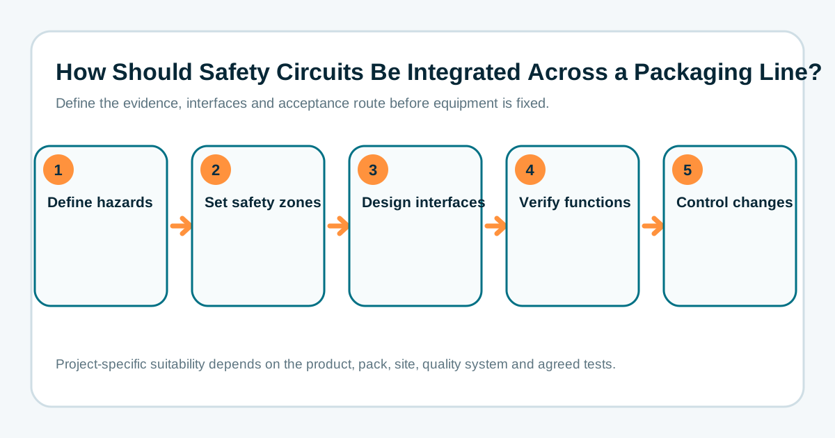
How Should Safety Circuits Be Integrated Across a Packaging Line? decision sequence

ANSWER FIRST

How should safety circuits be integrated across a packaging line?

Packaging-line safety circuits should be designed from the risk assessment for the complete assembly, including hazards created at the interfaces between individual machines. The project must define safety zones, guard and access functions, emergency-stop effects, reset locations, restart conditions and the response of upstream and downstream equipment. Connecting several compliant machines does not by itself prove that the combined line is safe.

The correct safety architecture and required performance depend on the actual hazards, stopping behaviour and applicable assessment. This guide explains project questions; it is not a substitute for competent machinery-safety design and validation.

Safety-interface decisions for an integrated line
DecisionProject questionEvidence
Safety zonesWhich hazards and machines are controlled together?Zone drawing and safety-function list
Guards and accessWhat must stop before a person can enter, and what remains energised?Guard schedule, access method and safe-state definition
Emergency stopWhat equipment is affected and can stopping create another hazard?Cause-and-effect matrix and stopping assessment
Reset and restartWho can reset, from where, and how is unexpected restart prevented?Reset philosophy, visibility review and test protocol
Machine interfacesWhich safety-related signals cross equipment boundaries?Interface-control document and validation record

ENGINEERING QUESTIONS

Questions to answer before the line controls are finalised

Should one emergency stop stop the whole line?

Not automatically. The affected scope should come from the risk assessment and the hazards created by continuing or stopping each section. A local emergency stop may need to stop adjacent machinery, while a plant-wide stop can create other risks or unnecessary recovery problems. The cause-and-effect should be documented and tested for each zone.

What is the difference between a normal stop and an emergency stop?

A normal production stop manages the process and is expected during routine operation. An emergency stop is a complementary protective measure for an emergency situation and should not be used as the normal control strategy. The line should have clear normal stop, fault stop, safety stop and emergency recovery behaviour.

How should guard doors affect neighbouring machines?

The response depends on which hazards can be reached through the opened access and whether product or energy can enter the zone from another machine. The project should define the safe state, prevent unexpected movement and consider stored pneumatic, electrical, gravitational or process energy, not only the nearest motor.

Where should reset controls be located?

Reset should confirm that the safety function can be restored; it should not create an automatic production restart. The location should support visibility of the relevant zone and the project's safe-start procedure. Larger or obscured areas may need additional measures defined by the risk assessment.

What changes when existing machines are integrated?

Existing safety circuits, documentation, stopping performance and access arrangements must be surveyed before interface design. Adding conveyors, bypassing old controls or changing guard boundaries can create new hazards and may change the conformity or PUWER assessment needed for the resulting assembly.

How should safety functions be accepted?

Acceptance should trace each agreed safety function to a test, expected result and record. Tests should include devices, signals, fault response, reset, restart, zone interactions and relevant stopping behaviour. The competent party responsible for verification and final documentation should be named in the project responsibility matrix.

Safety deliverables to define in the project scope

  • Assembly boundary and machinery-interface list
  • Risk-assessment responsibility and review stages
  • Safety-zone drawing and access schedule
  • Safety-function and cause-and-effect matrix
  • Guarding, isolation and stored-energy assumptions
  • Reset, restart and fault-recovery philosophy
  • Validation protocol, records and technical-file responsibility
  • Change-control route for later format or equipment modifications

Coordinate these decisions with the controls architecture guide and the packaging-line safety and risk-assessment guide.

Information to prepare for a useful discussion

Send the product and pack formats, target output, available footprint, existing machinery, site requirements and the evidence expected at acceptance. Lancing can then assess the project boundary, required trials and the most appropriate next engineering step.

Get line advice

Authoritative references for project teams

These sources support the general planning context. The final specification, risk assessment, quality-system decision and legal responsibilities remain project-specific.