
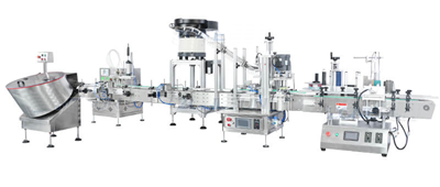
Turn separate machines into one predictable operating system by agreeing line states, interface signals, recipe ownership, quality responses and evidence before software is finalised.
1. Start with a line-level operating narrative
A controls specification should describe how the complete line behaves, not only which PLC is fitted to each machine. Write the sequence from the operator’s point of view: preparation, start-up, normal running, controlled stopping, completion, changeover, cleaning, maintenance and recovery from an interruption.
Use consistent state names and define what each state means at line level. The equipment suppliers can then map their internal machine states to the agreed line behaviour without forcing every machine to use identical software.
| Line condition | Controls question | Evidence required |
|---|---|---|
| Ready | Which utilities, guards, materials, recipes and downstream permissions must be healthy? | Permissive list and witnessed readiness check |
| Starting | Which modules start first and how is product released into the sequence? | Start sequence and dry-cycle test |
| Running | Which machine sets the line rate and how are short variations absorbed? | Line-control narrative and observed production run |
| Held or stopped | Does product remain in process, complete safely or require controlled clearance? | Defined stop categories and restart test |
| Faulted | Which fault is shown as the first cause and which modules must stop? | Alarm hierarchy and fault-injection test |
| Completing | How does the line empty without creating unlabelled, uncapped or unverified packs? | End-of-batch sequence and count reconciliation |
2. Define every machine-to-machine handshake
At each transfer point, identify what the upstream machine needs to know, what the downstream machine can accept and how quickly the line must react. A single “run” signal is rarely enough for a connected line. Typical information can include ready, running, fault, starved, blocked, product present, reject active and permission to transfer.
Separate production handshakes from safety functions. Emergency stops, guard circuits and safety-related resets require a competent risk assessment and an agreed safety architecture; they should not be treated as ordinary status bits.
| Field | What to record | Why it matters |
|---|---|---|
| Physical boundary | Transfer point, pack orientation, conveyor ownership and sensor position | Prevents mechanical and controls scope gaps |
| Signal direction | Source, destination, normal state and loss-of-signal response | Supports unambiguous I/O design |
| Timing and persistence | Whether a signal is momentary, maintained, filtered or acknowledged | Reduces intermittent transfer faults |
| Failure response | Stop, hold, complete cycle, reject, alarm or controlled run-down | Defines predictable abnormal behaviour |
| Test method | Simulation, dry run, product challenge or site-interface test | Connects design to acceptance evidence |
3. Decide where recipes and format authority live
A multi-format line needs one controlled answer to the question “which format is running?”. The architecture may use a line-level master recipe, coordinated local recipes or a verified manual selection on selected modules. Whichever route is chosen, define how format identity is transferred, how incompatible selections are prevented and who may change protected parameters.
- Assign a unique format identifier across the line.
- Record which parameters are automatic, prompted or mechanically verified.
- Define how recipe changes are approved and backed up.
- Confirm what happens if one machine does not contain the requested format.
- Include coding, inspection and reject settings in the changeover check.
- Keep product and packaging-component versions aligned with the selected recipe.
4. Specify alarms, rejects and quality responses as complete functions
Each alarm should identify the first actionable condition rather than create a cascade of secondary messages. Decide which events stop one machine, hold the line, require controlled clearance or permit continued production. For repeated short stops, record enough context to show where the event began.
For every automated quality check, define the detection point, the reject action and the confirmation that the rejected pack was removed. Also define the response to a full reject bin, failed reject confirmation, missing code data or an unavailable inspection device.
- No-container-no-fill and no-closure responses
- Reject confirmation and reject-bin capacity monitoring
- Code-data availability and verification
- Alarm priority, first cause and operator guidance
- Controlled reset conditions after a guard or fault event
- Count reconciliation between produced, rejected and accepted packs
5. Agree the data model before connecting higher-level systems
Start with the operational decisions the data must support. Production counts, good packs, rejects, line states, stop causes, recipe identity and alarm history are useful only when their definitions and count points are consistent. Agree time synchronisation, data ownership, retention and the boundary between machinery controls and site systems.
Where a standardised machine-state model is appropriate, PackML is one recognised industry approach. The official OMAC PackML resources describe common machine states and data concepts. Adoption should be specified deliberately; a logo or compatible PLC does not replace an agreed implementation scope.
| Data item | Definition to agree | Common ambiguity |
|---|---|---|
| Good count | Exact count point and quality status | Counting before a later reject |
| Stop duration | Start, end and treatment of micro-stops | Different clocks or thresholds by machine |
| First cause | Rule for assigning the initiating event | Every blocked machine reporting the same event |
| Format | Controlled identifier and revision | Local names that do not match line-level records |
| Production order | Source, validation and fallback procedure | Unclear ownership between HMI and site system |
6. Keep the safety architecture explicit
The production-control narrative and the safety function specification must agree on stop, reset and restart behaviour. Define guarding zones, access needs, emergency-stop effects, stored energy, reset locations and the circumstances in which automatic restart is prohibited. A competent machinery risk assessment should determine the required protective measures and safety-related control performance.
Use the separate packaging line safety and risk-assessment guide to organise buyer inputs, and confirm the final design with competent safety specialists.
7. Build an approval and test pack for the controls scope
Controls work becomes easier to manage when each design document has an owner, revision and acceptance route. Keep the line-control narrative, interface schedule, I/O list, alarm list, recipe matrix, HMI conventions, safety-function specification and data map aligned.
- Approved line sequence and operating modes
- Machine-interface and network schedule
- Recipe, access and backup responsibilities
- Alarm, reject and recovery scenarios
- Safety-zone and reset philosophy
- Production-data definitions and count points
- Factory and site test cases linked to each critical requirement
Continue with the FAT and SAT readiness guide to turn the controls design into witnessed evidence.