
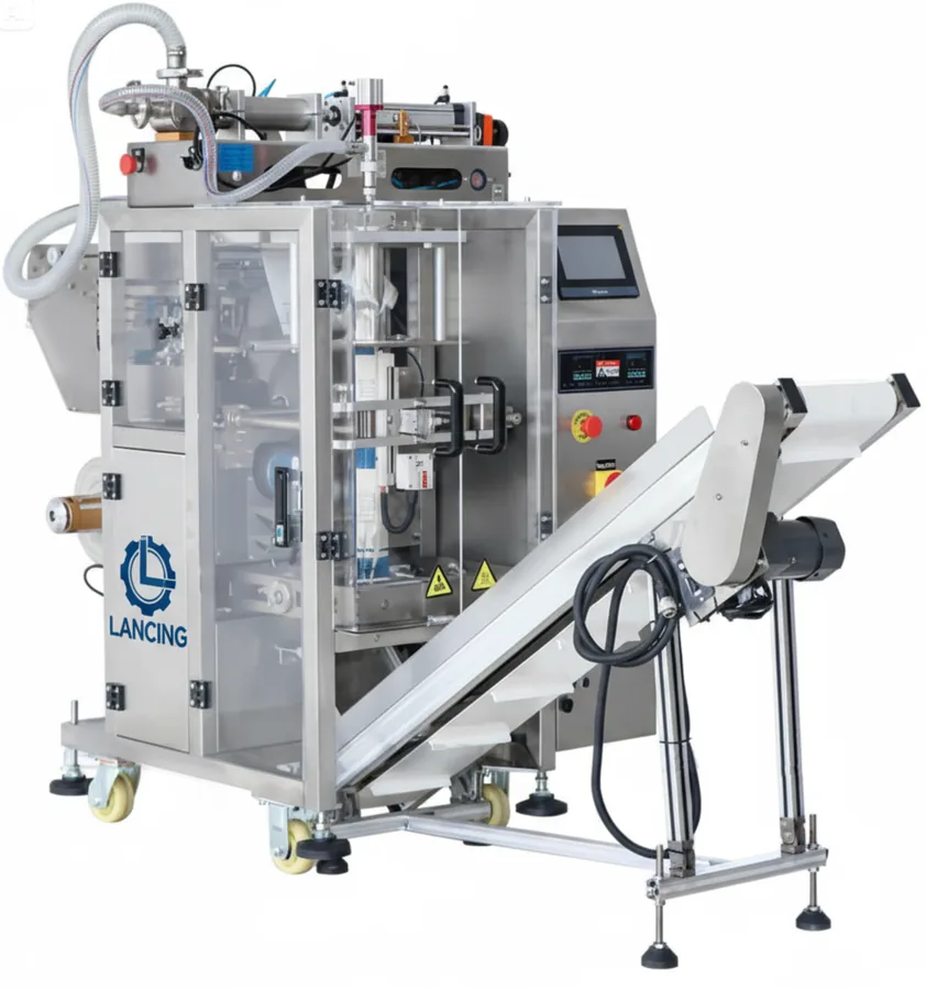
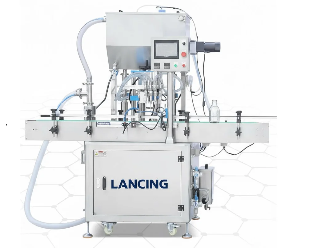
One connected production system

Automatic Packaging Line Integration

Coordinate machinery, conveyors, controls, guarding, utilities and pack flow so separate modules operate as a practical automatic packaging line.

  • Application-led specification
  • Connected line engineering
  • UK installation and support
Packaging line integration around automatic machinery
40+ yearspackaging machinery experience
One production sequenceModules planned as a connected system
Built around your packsProduct, container and closure first
Practical UK supportFrom specification to aftercare

Your production requirement

Resolve the interfaces before equipment reaches site

Integration covers the spaces and decisions between machines: pack transfer, rates, buffering, signals, guarding, access, utilities, rejects and responsibility for the final line response. These are frequent sources of delay when equipment is bought in isolation.

Lancing Ltd can help define the line sequence, survey existing assets, develop the layout and coordinate an agreed machinery package from specification through commissioning and handover.

Line architecture

Integration scope for new and existing lines

The project boundary is documented so each mechanical, electrical and operational interface has an owner.

Process and layout

Map the production sequence, pack path, operator zones, utilities and future expansion.

Mechanical interfaces

Coordinate heights, transfers, guides, accumulation, guarding and access.

Controls interfaces

Define run permissives, stop categories, status signals, recipes and line response.

Acceptance and handover

Test agreed formats, record settings, train operators and close documented actions.

Automatic packaging line machinery

Specification checklist

Bring all stakeholders into the line brief

Production, engineering, quality, safety and maintenance each see different constraints that affect the design.

  • Process flow and line boundary
  • Existing machine details and available documentation
  • Pack, product and component format matrix
  • Performance target and acceptance method
  • Site access, utilities, safety and integration standards
  • Responsibilities for installation, services and validation

Your project route

What you can expect from first discussion to production

  1. 1

    Share

    Tell us the product, pack formats, output target, shifts, site constraints and future plans.

  2. 2

    Test

    We review representative product, containers, closures and labels so recommendations are based on real production materials.

  3. 3

    Plan

    You receive a coordinated line concept covering machinery, transfers, controls, guarding, access, utilities and changeovers.

  4. 4

    Install

    We support installation, integrated testing, settings, operator training and production handover against the agreed scope.

  5. 5

    Support

    You can plan servicing, critical spares, new formats and future improvements around production risk.

Operational value

A coordinated route from scope to production

Fewer interface gaps

Mechanical, controls and responsibility boundaries are identified before installation.

One line layout

Equipment positions, access and product flow are developed together.

Measured handover

Acceptance checks focus on the agreed integrated duty and pack formats.

Start with your product and production goal

Get a packaging line recommendation for your operation

Tell us what you pack, the container and closure, your target output and the space available. We will help you identify the right line sequence and level of automation.

Straight answers

Frequently asked questions

Can you integrate machinery from different manufacturers?

Potentially. Technical information, controls, safety interfaces, speeds and support arrangements must be available and compatible with the intended line.

Can existing equipment be included?

Yes, subject to survey and assessment of condition, performance, controls, dimensions and suitability for the new duty.

What is included in a line-integration survey?

It may include layout measurements, machine interfaces, utilities, access, pack flow, controls, safety boundaries and discussions with the operating team.

Who owns overall line performance?

That should be stated in the contract and acceptance plan. Clear scope and performance assumptions prevent uncertainty between individual machines and the integrated line.

Next steps

Interface ownership and controls architecture

Create one responsibility matrix for the complete automatic line

Line integration is strongest when every boundary has an owner and an acceptance method. The matrix should cover mechanical transfers, electrical supplies, controls signals, safety functions, utilities, product and component supply, data, rejects, surrounding structures and downstream handover.

A line-level controls description should then explain how modules interact. It does not need to prescribe every software detail, but it should define states, permissives, starved and blocked behaviour, controlled stops, fault recovery, manual modes, recipe ownership and the response to failed inspection.

Automatic packaging-line interface schedule
Interface familyQuestions to closeEvidence before handover
MechanicalWorking heights, transfer ownership, guide continuity, access and change partsRepresentative packs transfer through each boundary in agreed modes
Electrical and controlsPower boundary, signals, network, states, alarms, recipes and dataI/O and functional tests demonstrate normal, fault and recovery behaviour
SafetyRisk-assessment boundary, guarding, emergency stops, interlocks and restartRecorded validation of agreed safety functions by competent parties
Process and qualityProduct feed, components, codes, inspections, rejects and finished-pack handoverComplete packs meet the agreed acceptance criteria and failed packs are contained

Information to prepare

  • Approved process flow and layout
  • Interface and responsibility matrix
  • Controls and line-state description
  • Safety and guarding boundary
  • Product, pack and format evidence
  • Acceptance, training and document schedule

Continue the project

Use the related pages to turn this guidance into a clearer scope and a more useful technical discussion.

Additional buyer questions

Project questions to agree before order

What is a machine-to-machine handshake on a packaging line?

It is the agreed exchange of states or signals that allows connected equipment to coordinate readiness, running, starvation, blockage, faults, stops and restart without relying only on conveyor motion.

What belongs in an interface responsibility matrix?

Include mechanical transfers, electrical supplies, controls signals, safety zones, utilities, product and component supply, inspection and reject handling, data, site works, testing and final handover.

How can integration risk be reduced before equipment reaches site?

Use representative samples, a measured layout, approved interface drawings, an assumptions register, agreed control behaviour and factory tests that challenge normal and selected fault conditions.

Interface control in detailed engineering

Control every machine boundary with an interface control document

A responsibility matrix identifies who owns an interface. An interface control document goes further by recording exactly what crosses the boundary, which drawing or signal list defines it, what each party must supply, how changes are approved and how completion will be verified.

Give each boundary a unique reference and keep the same reference on layouts, electrical drawings, I/O schedules, software descriptions, risk-control records and test sheets. This creates a traceable route from the quoted scope to the installed line.

Information to control at a packaging-line machine boundary
Interface familyDefinition packageClosure evidence
Mechanical transferDatums, working heights, conveyor overlap, guide continuity, pack pitch, support, adjustment range and change partsApproved interface drawing and witnessed transfer of representative packs in required modes
Electrical and controlsPower boundary, isolators, I/O, network, master commands, line states, alarms, recipes, counts and time synchronisationPoint-to-point checks plus functional tests of normal, starved, blocked, fault and recovery behaviour
SafetyRisk-assessment boundary, guarding ownership, access points, emergency-stop zones, safe signals, reset locations and validation responsibilityRecorded verification and validation of the agreed safety functions by competent parties
Utilities and environmentCompressed air, extraction, drainage, product services, temperature, washdown, floor loading and connection pointsSite-readiness record and measured confirmation before commissioning
Process and qualityProduct condition, pack presentation, code source, inspection criteria, reject route, sampling and downstream acceptanceApproved trial evidence and demonstrated pass, fail and containment responses
Data and ownershipRequired production records, protocols, access rights, backups, software ownership and change controlApproved configuration index, backup record and witnessed data exchange where included

Minimum interface-control fields

  • Unique reference and physical location
  • Supplier and customer owners
  • Inputs, outputs and approved source documents
  • Operating, fault and recovery requirements
  • Safety and quality implications
  • Verification stage, record and status
  • Revision, change reason and approval

Carry interfaces through to commissioning

Use the same controlled records during site readiness, functional testing and handover so unresolved boundaries do not disappear between suppliers or project stages.

Controls and interface definition

Approve the machine boundaries before detailed integration begins

Each mechanical transfer, production signal, safety boundary, utility connection and data exchange needs a named owner and a test route. This prevents the integrator from discovering incompatible assumptions during commissioning.

Interface approval record
BoundaryMinimum recordClosure evidence
Mechanical transferOwnership, pack orientation, height, speed and guide arrangementApproved drawing and product transfer test
ControlsSignal source, destination, normal state and failure responseI/O and functional test
SafetyZone, protective function, reset and retained-equipment effectCompetent validation record
Utility or processSupply quality, connection point, isolation and responsibilitySite readiness and commissioning check
DataSource, format, network, ownership and fallback routeInterface test and approved record

Interface questions

Questions buyers ask about packaging line integration

What is the minimum information needed for a machine-interface review?

Provide working heights, transfer geometry, product condition, available signals, utility boundaries, safety zones, operating modes and the expected response to starved, blocked and fault states. Drawings should be checked against the actual machine where retained equipment is involved.

How should working-height differences between machines be managed?

Use a designed transfer that maintains product stability and access while respecting each machine’s approved infeed and outfeed conditions. Adjustable conveyors, change in elevation or intermediate handling may be possible, but the route should be trialled for the most unstable formats.

How are shared faults and resets tested across a line?

Challenge each interface deliberately and confirm the first alarm, stop boundary, product condition, reset permissions and restart sequence. Include loss of signal and unavailable-equipment cases, not only normal production. Link the test to the approved interface schedule.

What is the difference between integration scope and equipment supply scope?

Equipment supply lists the items provided; integration scope defines how those items become one operating system. Integration covers transfers, controls, safety, layout, tests and responsibility at boundaries. See turnkey scope and integrator responsibilities.

Integration boundary

Include data, backups and lifecycle support in the interface register

Mechanical transfers and run signals are only part of line integration. The project also needs a controlled boundary for production data, software ownership, diagnostics and support after handover.

Define the reporting interface before software is finalised

Start with the decisions the customer needs to make rather than requesting every available PLC tag. Agree the source and meaning of good counts, rejects, line states, alarms, recipe identity and first-cause stop data. Identify whether the information remains at local HMIs, is consolidated by a line controller or is transferred to a site reporting, OEE, SCADA or MES system.

Record the interface method, update behaviour, time source, network boundary, ownership and test evidence. A valid data connection is not the same as a useful report: count points and state definitions must be consistent across the line.

Make supportability an integration deliverable

List the PLC, HMI, drive, vision, coder and inspection configurations that require controlled backups. Define who holds each backup, how revisions are approved and how a restore will be tested without creating an uncontrolled production or safety change. Remote support, where required, should follow the customer’s operational-technology security policy and an agreed access process.

Lifecycle interface register
InterfaceQuestions to closeEvidence
Production dataWhich count point, state model and stop cause is authoritative?Data dictionary and witnessed report
NetworkWho supplies addressing, switches, ports, segmentation and remote-access approval?Approved architecture and connection test
SoftwareWhich backups, versions, licences and credentials are handed over?Controlled backup register and restore check
SparesWhich common components can stop the line and what is the sourcing route?Criticality review and approved spares list
SupportWho diagnoses each boundary and what evidence is needed before escalation?Support responsibility matrix

Use the packaging line data-integration guide to define reporting requirements and the maintenance and critical-spares guide to prepare the lifecycle support scope.

Packaging Line Cybersecurity and Remote Support explains the project decisions, evidence and responsibilities that should be resolved before the relevant line scope is accepted.

Packaging Line Project Responsibility Matrix explains the project decisions, evidence and responsibilities that should be resolved before the relevant line scope is accepted.

ADDITIONAL INTERFACE GUIDANCE

Define data, safety and downstream automation in the same interface register

Modern line projects can cross mechanical, controls, safety, data and logistics boundaries. Use one responsibility model to show who supplies each signal, device, document, test and approval.